s3stasher simplifies using AWS S3 in python

Working with cloud files in python is a necessary pain at any biotech organization. While packages like pandas transparently handle S3 URIs, I still found myself writing the same boto3 code to manage files far too often. Nextflow solves this for workflows, but there aren’t any packages that I’m aware of that make managing S3 files easier for script and notebook use cases.

I developed s3stasher to make working with files in AWS S3 as easy if they were local files. The key principles are:

  • S3 objects should be referred to as full URIs at all times. It shouldn’t be necessary to split a URI into bucket and key strings.
  • Any method that reads or writes a file should transparently work on S3 URIs or local files.
  • S3 objects should be cached locally and only re-downloaded when the source object has changed.
  • Reading S3 objects should work identically while offline, assuming the user has the file cached.

Using s3stasher, you simply have to wrap any file reading or writing in a with statement, and all the file operations will happen behind the scenes.

from s3stasher import S3

# Download, cache, and read an S3 object
with S3.s3open("s3://my-bucket/my_data.csv") as f:
    my_df = pd.read_csv(f)

# Two layers of context manager are needed for traditional open operations
with S3.s3open("s3://my-bucket/unstructured.txt") as s3f:
    with open(s3f) as f:
        lines = f.readlines()

# Write a file back to s3. By default, it will be saved in the cache dir 
# to avoid an unnecessary download in the future
with S3.s3write("s3://my-bucket/my_data_new.csv") as f:
    my_df.to_csv(f)

# Other convenience functions are provided
## List objects under a prefix
uri_list = S3.s3list("s3://my-bucket/prefix/")
## Check for existance of an object
uri_exists = S3.s3exists("s3://my-bucket/unknown_file.txt")
## copy, move, remove an S3 object
S3.s3cp("s3://my-bucket/my_file_1.txt", "s3://my-bucket/my_file_2.txt")
S3.s3mv("s3://my-bucket/my_file_2.txt", "s3://my-bucket/my_file_3.txt")
S3.s3rm("s3://my-bucket/my_file_3.txt")

By default, s3stasher uses your already set up AWS credentials, and caches files to ~/.s3_cache. All of these options can be changed with a config file or environment variables.

You can install s3stasher with a quick pip install s3stasher.
Pypi: https://pypi.org/project/s3stasher/
GitHub: https://github.com/bsiranosian/s3stasher

Feedback and PRs welcome!

Does AMD 3D V-Cache help in bioinformatics?

Introduction

In our new office at Pattern, I have 42U of server rack space to play with, so I want to get an AMD EPYC server for some long-running bioinformatics tasks. EPYC Genoa looks like the sweet spot for price to performance, but which of the 24 SKUs is the best for typical bioinformatics workloads? Obviously, more cores and more frequency is more better, but are there additional factors to consider?

Specifically, I’m interested in comparing the 9654 and 9684X CPUs. Both are 96-core, 192 thread monsters that can boost up to 3.7 GHz, but the 9684X has over a gigabyte of L3 cache, three times that of the 9654. That’s AMD 3D V-Cache, which became famous through it’s use in gaming desktop CPUs and has now made its way to the server market. 3D V-Cache is also supposed to help certain productivity workloads, but there’s not many benchmarks that cover bioinformatics specifically. The only mention I could find was this post on Mark Ziemann’s blog.

AMD 3D V-Cache diagram

The cache is stacked on top of the processor … in 3D!

In this post, I benchmark a few common bioinformatics tools with the AMD 7950X3D processor, which has both 3D V-Cache and normal cores. In the end, I’m surprised to find a little to no increase in performance when running on the 3D V-Cache cores, at least for the algorithms I tested.

Methods

  • Processor: AMD Ryzen 9 7950X3D: 16-core / 32-thread. 2 × 8‑core Core Complex Dies (CCDs). One CCD has 3D V-Cache. 128 MB L3 cache total, split 96/32 across the different CCDs.
  • BIOS setup: For the V-Cache test, I disabled the non‑V-Cache CCD in BIOS. The reverse was done for the non V-Cache test.
  • Operating system: Ubuntu 22.04.
  • Other hardware: 2TB M.2 SSD, 96GB RAM. Memory overclocking and Precision Boost Overdrive (PBO) were disabled for this test.
  • The V-Cache CCD boosts up to ~4.8 GHz under load, but the non V-Cache CCD can reach ~5.8GHz. To control for frequency, I ran a third test locking the non‑V-Cache CCD at 4.8 GHz via the cpupower command.
  • Bioinformatics tools: We do a lot of short and long-read alignment, so I used minimap2, STAR, and a full run of the nf-core/RNAseq pipeline. All with real-world data from one sample.
  •  Measurement: Wall time for the completion of the single command or entire pipeline. Average of 3 replicates reported for each test. The results of each test were surprisingly tight, within a few seconds. The same datasets and command were used for each test. Non-essential background processes as possible were closed during the test.

Results

Processor sectionSTAR (s)minimap2 (s) nf-core/RNAseq (m)
V-Cache CCD 4.8 GHz36849360.1
Non V-Cache CCD 5.8 GHz
35442754.2
Non V-Cache CCD 4.8 GHz38446963.2
V-Cache improvement compared to 5.8 GHz-3.8%-15.5%-10.9%
V-Cache improvement compared to 4.8 GHz4.2%-5.1%4.9%

These results were quite interesting. 3D V-Cache offers a modest improvement compared to a frequency-matched processor, but only for certain tools and workflows. When the non V-Cache CCD was allowed to use the full 5.8GHz, it was always the winner.

Conclusions

For alignment-based bioinformatics tasks, a processor with 3D V-Cache may gain a task-dependent and small improvement in runtime. These improvements were completely negated by a higher-frequency processor. This is nowhere near the halving of runtime seen with computational fluid dynamics and other workloads.

Buying the more expensive and higher powered EPYC 9684X likely isn’t worth it for my use case. I need to learn more about how these algorithms take advantage of different CPU cache levels in order to attempt to explain these results. Additional investigation with AMD μprof might be helpful.

These results significantly more modest than what was reported at Genome Spot, although that post looked at Intel processors.

Limitations

These results could differ for other bioinformatics tasks, like variant calling. Additionally, I attempted to simulate the performance difference of two separate server processors by using different CCDs on my desktop processor. This method could give different results than separate server CPUs.

Deep learning to understand and predict single-cell chromatin structure

In my last post, I described how to simulate ensembles of structures representing the 3D conformation of chromatin inside the nucleus. Now, I’m going to describe some of my research to use deep learning methods, particularly an autoencoder/decoder, to do some interesting things with this data:

  • Cluster structures from individual cells. The autoencoder should be able to learn a reduced-dimensionality representation of the data that will allow better clustering.
  • Reduce noise in experimental data.
  • Predict missing points in experimental data.

Something I learned early on rotating in the Kundaje lab at Stanford is that deep learning methods might seem domain specific at first. However, if you can translate your data and question into a problem that has already been studied by other researchers, you can benefit from their work and expertise. For example, if I want to use deep learning methods on 3D chromatin structure data, that will be difficult because few methods have been developed to work on point coordinates in 3D. However, the field of image processing has a wealth of deep learning research. A 3D structure can easily be represented by a 2D distance or contact map – essentially a grayscale image. By translating a 3D structure problem into a 2D image problem, we can use many of the methods and techniques already developed for image processing.

Autoencoders and decoders

The primary model I’m going to use is a convolutional autoencoder. I’m not going into depth about the model here, see this post for an excellent review. Conceptually, an autoencoder learns a reduced representation of the input by passing it through (several) layers of convolutional filters. The reverse operation, decoding, attempts to reconstruct the original information from the reduced representation. The loss function is some difference between the input and reconstructed data, and training iteratively optimizes the weights of the model to minimize the loss.

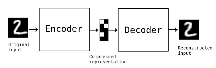
In this simple example, and autoencoder and decoder can be thought of as squishing the input image down to a compressed encoding, then reconstructing it to the original size (decoding). The reconstruction will not be perfect, but the difference between the input and output will be minimized in training. (Source)

Data processing

In this post I’m going to be using exclusively simulated 3D structures. Each structure starts as 64 ordered 3D points, an 64×3 matrix with x,y,z coordinates. Calculating the pairwise distance between all points gives a 64×64 distance matrix. The matrix is normalized to be in [0-1]. The matrix is also symmetric and has a diagonal of zero by definition. I used ten thousand structures simulated with the molecular dynamics pipeline, with an attempt to pick independent draws from the MD simulation. The data was split 80/20 between training and

Model architecture

For the clustering autoencoder, the goal is to reduce dimensionality as much as possible while still retaining good input information. We will accept modest loss for a significant reduction in dimensionality. I used 4 convolutional layers with 2×2 max pooling between layers. The final encoding layer was a dense layer. The decoder is essentially the inverse, with upscaling layers instead of max pooling. I implemented this model in python using Keras with the Theano backend.

Dealing with distance map properties

The 2D distance maps I’m working with are symmetric and have a diagonal of zero. First, I tried to learn these properties through a custom regression loss function, minimizing the distance between a point i,j and its pair j,i for example. This proved to be too cumbersome, so I simply freed the model from learning these properties by using custom layers. Details of the implementation are below, because they took me a while to figure out! One custom layer sets the diagonal to zero at the end of the decoding step, the other averages the upper and lower triangle of the matrix to enforce symmetry.

Clustering single-cell chromatin structure data

No real clustering here…

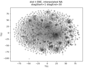
In the past I’ve attempted to visualize and cluster single-cell chromatin structure data. Pretty much any way I tried, on simulated and true experimental data, resulted the “cloud” – no real variation captured by the axes. In this t-SNE plot from simulated 3D structures collapsed to 2D maps, you can see some regions of higher density, but no true clusters emerging. The output layer of the autoencoder ideally contains much of the information in the original image, at a much reduced size. By clustering this output, we will hopefully capture more meaningful variation and better discrete grouping.


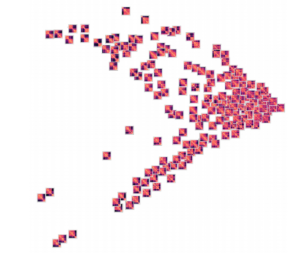
Groupings of similar folding in the 3D structure!

Here are the results of clustering the reduced dimensionality representations learned by the autoencoder. I’m using the PHATE method here, which seems especially applicable if chromatin is thought to have the ability to diffuse through a set of states. Each point is represented by the decoded output in this map. You can see images with similar structure, blocks that look like topologically associated domains, start to group together, indicating similarities in the input. There’s still much work to be done here, and I don’t think clear clusters would emerge even with perfect data – the space of 3D structures is just too continuous.

Denoising and inpainting

I am particularly surprised and impressed with the usage of deep learning for image superresolution and image inpainting. The results of some of the state of the art research are shocking – the network is able to increase the resolution of a blurred image almost to original quality, or find pixels that match a scene when the information is totally absent.

With these ideas in mind, I thought I could use a similar approach to reduce noise and “inpaint” missing data in simulated chromatin structures. These tasks also use an autoencoder/decoder architecture, but I don’t care about the size of the latent space representation so the model can be much larger. In experimental data obtained from high-powered fluorescence microscope, some points are outliers: they appear far away from the rest of the structure and indicate something went wrong with hybridization of fluorescence probes to chromatin or the spot fitting algorithm. Some points are entirely missed, when condensed to a 2D map these show up as entire rows and columns of missing data.
To train a model to solve these tasks, I artificially created noise or missing data in the simulated structures. Then the autoencoder/decoder was trained to predict the original, unperturbed distance matrix.

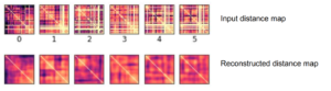
Here’s an example result. As you can see, the large scale features of the distance map are recovered, but the map remains noisy and undefined. Clearly the model is learning something, but it can’t perfectly predict the input distance map

Conclusions

By transferring a problem of 3D points to a problem of 2D distance matrices, I was able to use established deep learning techniques to work on single-cell chromatin structure data. Here I only showed simulated structures, because the experimental data is still unpublished! Using an autoencoder/decoder mode, we were able to better cluster distance maps into groups that represent shared structures in 3D. We were also able to achieve moderate denoising and inpainting with an autoencoder.

If I was going to continue this work further, there’s a few areas I would focus on:

  • Deep learning on 3D structures themselves. This has been used in protein structure prediction [ref]. You can also use a voxel representation, where each voxel can be occupied or unoccupied by a point. My friend Eli Draizen is working on a similar problem.
  • Can you train a model on simulated data, where you have effectively infinite sample size and can control properties like noise, and then apply it to real-world experimental data?
  • By working exclusively with 2D images we lose a lot of information about the input structure. For example the output distance maps don’t have to obey the triangle inequality. We could use a method like Multi-Dimensional Scaling to get a 3D structure from an outputted 2D distance map, then compute distances again, and use this in the loss function.

Overall, though this was an interesting project and a great way to learn about implementing a deep learning model in Keras!


Simulating 3D chromatin structure with molecular dynamics and loop extrusion

Much of the current evidence for the loop extrusion hypothesis comes from molecular dynamics simulations. In these simulations, DNA is modeled as a polymer, loop extruding factors with certain parameters are added into the mix, and the polymer is allowed to move around as if it were in a solvent. By running the simulation for a long time and saving conformations of the polymer at defined intervals, you can gather an ensemble of structures that represent how chromatin might be organized in a population of cells. Note that molecular dynamics is much different than MCMC approaches to simulating chromatin structure – here we’re actually simulating how a chromatin might behave due to physical and chemical properties.

In this post, I’m going to show you how you can run these molecular dynamics simulations for yourself. The simulations rely on the OpenMM molecular simulation package, the Mirnylab implementation of openmm-polymer and my own scripts and modification of the mirnylab code.

Ingredients

  • Install the required packages. See the links above for required code repositories. Note that it can be quite difficult to get openmm-polymer configured properly, so good luck…
  • Simulation is much quicker using a GPU
  • Pick your favorite chromatin region to simulate. In this example, we’re going to use a small region on chromosome 21.
  • Define CTCF sites, including orientation and strength. These will be used as blocking elements in the simulation. The standard is to take CTCF binding ChIP-Seq data for your cell type of interest, overlap the peaks with another track too add confidence and determine orientation (such as CTCF motifs in the genetic code or RAD21 binding data).
  • Define other parameters for the simulation, such as the time step and number of blocks to save. These can be found in the help text for the simulation script.

Check your parameters

Before running a time consuming 3D polymer simulation, you can run simple test to see how the extruding factors are behaving in the simulation. This 2D map gives the probability of an extruder binding two sites along the linear genome, and is a good prediction for how the mean 3D structure will look. Briefly, there’s a logistic scaling function that transforms an arbitrary ChIP-Seq peak strength into a 0.0-1.0 interval. The scaled strength of the each site defines the probability that a LEF can slip past the site without stalling. Even though CTCF might form an impermiable boundary in reality, modeling this with a probability makes sense because we’re generating an ensemble of structures. You might need to tune the parameters of the function to get peak strengths to make sense for your ChIP-Seq data.

Loop extruder occupancy matrix. This gives the log transformed probability of a LEF binding two locations along the genome. CTCF sites for the example region of interest are shown above, with the color indicating directionality and height indicating strength. Notice how we already start to see domain-like structures!

Running the simulation

With all the above ingredients and parameters configured, it’s time to actually run the simulation. Here we will run for a short number of time steps, but you should actually let the simulation run for much longer to gather thousands of independent draws from the distribution of structures.

Using the code available at my github, run the loop_extrusion_simulation.py script. Here is an example using the data available in the repository

cd openmm-dna
python src/loop_extrusion_simulation.py -i data/example_ctcf_sites.txt -o ~/loop_extrusion_test --time_step 5000  --skip_start 100 --save_blocks 1000

Some explanation of the parameters: time_step defines how many steps of simulation are done between saving structures, skip_start makes the script skip outputting the first 100 structures to get away from the initial conformation, save_blocks means we will save 1000 structures total. There are many other arguments to the script, check the help text for more. In particular, the –cpu_simulation flag can be used if you don’t have a GPU.

If everything is configured correctly, you’ll see output with statistics on the properties of each block.

potential energy is 3.209405
bl=1 pos[1]=[10.9 14.2 5.8] dr=1.46 t=8.0ps kin=2.39 pot=2.24 Rg=9.084 SPS=235
Number of exceptions: 3899
adding force HarmonicBondForce 0
adding force AngleForce 1
Add exclusions for Nonbonded force
Using periodic boundary conditions!!!!
adding force Nonbonded 2
Positions...
loaded!
potential energy is 2.354693
bl=2 pos[1]=[11.4 14.1 6.0] dr=1.21 t=8.0ps kin=1.78 pot=2.09 Rg=9.278 SPS=333
...

Processing simulated structures

After simulation, I process the raw structures by trimming the ends (by the same amount of the –extend argument) and binning the points by taking the 3D centroid to reduce the resolution. As I’m trying to match experimental data with this simulation, I reduce the resolution to the same as the experimental data. Then I save the ensemble in a numpy array, which is much quicker to load for subsequent analysis. There’s a script to do this:

python src/process_simulated_structures.py -i ~/loop_extrusion_test -o ~/loop_extrusion_test/processed

Analysis of results

There are a few ways you can analyze the results after the simulation has finished. The obvious first step is to create an average contact map from the ensemble of structures. This plot is the most comparable to a Hi-C dataset.

Simulation contact probability at radius of 10. 1000 structures went into this plot.

Hi-C contact frequency for the same region in K562 cells. A great qualitative match, inluding domains and peaks!


Another common way to look at chromatin structure data is plotting contact probability as a function of genomic distance. This function is expected to decrease linearly on a log-log plot, with the slope giving evidence for mechanism for packing the underlying structures. You can look at the radius of the structures, how they cluster, and many other metrics. More on this to come later!

Publishing code on GitHub

This semester, I’ve made an effort to get all the code I write under version control. In the past I simply maintained my codebase in Dropbox. This worked well as a backup solution and allowed me to develop the same project on my laptop and desktop without any problems (despite dealing with differences in Windows/Linux file paths). However, I’ve been involved in more collaborative coding projects this semester and Dropbox simply doesn’t cut it anymore.

Bioinformaticians as a group seem to be particularly passionate about version control and open access software – Titus Brown even says, ” If you can’t be bothered to learn how to use version control, you shouldn’t be trusted to write important software.” This goes along with the open source and open access movement academics generally tend to support. Plus, we’ve all had the experience of working with poorly maintained, documented or commented code… It can really slow down the research process and be a huge hassle.

So, I’ve made a new commitment. Every piece of code I write for an academic project will be under version control on GitHub. Code for lab work that we’ve decided to publish will also make its way there (for the time being it’s held in a private bitbucket repository, still under version control though!) This is a bit of a challenge for me – publishing code is a lot like publishing something you’ve written. You’re putting your work out there for the world to see and critique, and in a lot of cases, it’s not a finished product or something you’re quite happy with yet.

I see a lot of advantages to making code public. It should help me develop better structured, more thoughtful and well-commented code. It will allow me to share projects and ideas with anyone just by giving them my GitHub username (hint: it’s bsiranosian). I can now include my GitHub url on things like my website and business cards, and anyone can see the kind of projects I work on. I feel like this could give me a leg up when searching for jobs and the like.

I can see a few downsides too. Academic integrity is one – I don’t want someone at Brown or another university copying my code for their homework or project. After thinking about this point though, I realized the answers to most bioinformatics problems are already available at places like stackoverflow. It’s not my responsibility to make sure someone doesn’t plagiarize code. Titus Brown teaches an undergraduate class where students are required to hand in assignments on GitHub and hasn’t had any problems.

You can find my GitHub at https://github.com/bsiranosian